TM-9-2350-311-20-1 - Page 1089 of 1275
TM 9-2350-311-20-1
13-5 PORTABLE FIRE EXTINGUISHER MOUNTING BRACKET, PROJECTILE SPACER BOX,
AND RIFLE STOWAGE CLIPS — CONTINUED
a. Removal — Continued
NOTE
Steps 2 and 3 apply to projectile spacer box.
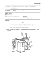
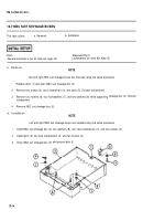
2 Remove projectile spacers (4) if present.
NOTE
Some projectile spacer boxes may have screws and Iockwashers located on back of
box instead of on bottom of box.
3 Remove four screws (5), four Iockwashers (6), and projectile spacer box (7). Discard Iockwashers.
NOTE
Steps 4 and 5 apply to rifle stowage clips.
4 Remove four screws (8), four Iockwashers (9), four rifle stowage clips (10), eight washers (11), and four straps
(12) in crew compartment. Discard Iockwashers.
5 Remove screw (13), Iockwasher (1 4), rifle stowage clip (15), and strap (16) in driver’s compartment. Discard
Iockwasher.
b. Installation
NOTE
Steps 1 and 2 apply to rifle stowage clips.
1 Install strap (16), rifle stowage clip (15), new lockwasher (14), and screw (13) in driver’s compartment.
2 Install four straps (12), eight washers (11), four rifle stowage clips (10), four new Iockwashers (9), and four
screws (8) in crew compartment.
NOTE
. Locations of portable fire extinguisher mounting bracket and projectile spacer box
differ on M109A2/M109A3 and M109A4/M109A5 Howitzers. The following
procedures apply no matter where the location. M109WM1O9A3 shown.
l Steps 3 and 4 apply to projectile spacer box.
l Some projectile spacer boxes may have screws and Iockwashers located at back
of box instead of at bottom of box.
3 Install projectile spacer box (7), four new Iockwashers (6), and four screws (5).
13-10
Back to Top


