TM-9-2350-311-20-1 - Page 1095 of 1275
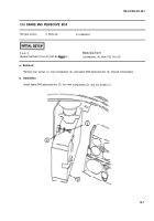
14-1 WINTERIZATION KIT DIAGRAM
NOTE
This installed view of the winterization kit identifies all items in the kit. Those items
which only need to be disconnected during powerplant removal are identified by a
single asterisk (*). Those items that need to be removed during powerplant removal
are identified by a double asterisk ~*).
LEGEND
1
2
3
4
5
6
7
8
9
10
11
12
13
14
15
Connector (wire 459B) to MASTER switch
Receptacle at driver’s compartment bulkhead
Bulkhead-to-heater, fuel pump, and coolant
pump harness (wires 402B, 402C, 403B, 403C,
406, and ground)*
Battery insulation box
Battery heater plate parts
Exhaust outlet plug
Exhaust outlet
Transmission left access door
Exhaust tube**
Heater-to-surge tank hose connector tube*
Fuel pump-to-heater fuel tube*
Coolant heater**
Fuel pump (electric)**
Fuel filter-to-fuel pump fuel tube**
Fuel filter**
16
17
18
19
20
21
22
23
24
25
26
27
28
29
30
Primary fuel filter-to-fuel filter fuel hose*
Coolant pump (electric)**
Engine coolant surge tank hose
Heater hose-to-surge tank hose Y-connector tube
Coolant pump-to-heater hose
Engine coolant manifold-to-battery heater inlet
hose*
Engine manifold
Primary fuel filter
Primary fuel filter-to-engine fuel tube
Fuel tank-to-primary fuel filter hose
Heater lead (wire 400)
Heater control box
Control box-to-master switch and bulkhead
harness (wires 400, 402B, 402C, 406, and 459B)
MASTER switch (reference)
Battery heater outlet-to-coolant pump hose*
14-2
TM9-2350-311-20-1
Back to Top


