TM-9-2350-311-20-1 - Page 1105 of 1275
TM 9-2350-311 -20-1
14-7 COOLANT HEATER
This task covers:
a. Removal
b. Installation
INITIAL SETUP
References
General mechanic’s tool kit (item 64, Appx H)
TM 9-2350-311-10
Lockwasher (item 95, Appx G)
Fuel inlet-to-fuel tank hose quick disconnect at primary fuel
filter disconnected (para 6-6)
Batteries disconnected (para 8-28)
a. Removal
1
2
3
4
5
6
7
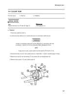
Disconnect wiring harness (1) at coolant heater (2) plug.
WARNIN G
Coolant is a hazardous waste and must be disposed of in accordance with local
procedures or direction of the local Hazardous Waste Management office.
NOTE
If hoses are not plugged and outlet is not capped, coolant system must be drained
(TM 9-2350-311 -10).
Loosen clamp (3) from coolant outlet hose (4) and disconnect hose from coolant heater (2). Cap heater coolant
outlet (5) with a short piece of 5/8-in. - (16-mm-) id hose and 5/8-in. - (16-mm-) diameter plug.
Loosen inlet hose clamp (6) and disconnect coolant inlet hose (7). Install 5/8-in. - (16-mm-) diameter plug in
coolant pump (8) outlet.
Disconnect fuel pump-to-coolant heater tube (9) at coolant heater (2).
Remove screw (10), Iockwasher (11), and bracket clamp (12). Discard Iockwasher.
Remove four nuts (13), four flat washers (14), four screws (15), and two coolant heater upper brackets (16).
NOTE
Coolant heater must be lifted or tilted in order to reach exhaust tube clamps.
Loosen exhaust tube clamp (17) at heater exhaust hose (18) and disconnect hose. Remove coolant heater (2)
from hull.
14-12
Back to Top


