TM-9-2350-311-20-1 - Page 118 of 1275
TM 9-2350-311-20-1
3-3 TROUBLESHOOTING CHART — CONTINUED
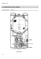
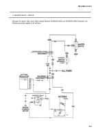
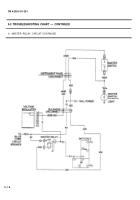
b. MASTER RELAY CIRCUIT — CONTINUED
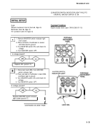
(1) MASTER SWITCH INDICATOR LIGHT IS LIT
Tools
General mechanic’s tool kit (item 64, Appx H)
Multimeter (item 36, Appx H)
TA-1 probe kit (item 43, Appx H)
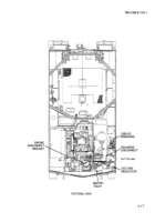
Engine access doors open (TM 9-2350-311-1O)
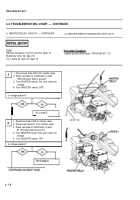
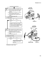
A
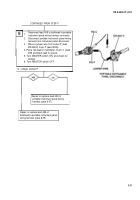
1. Disconnect lead 459 from master relay.
2. Place red lead of multimeter in lead
459 and black lead to ground.
3. Turn MASTER switch ON, and check for
voltage.
4. Turn MASTER switch OFF.
Is voltage present?
Go to step E.
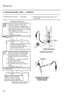
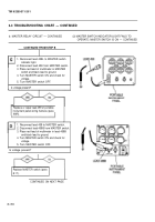
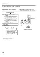
B
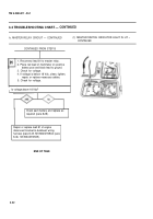
1. Reconnect lead 459 to master relay.
2. Disconnect lead 81 from master relay.
3. Place red lead of multimeter in lead
81 and black lead to ground.
4. Turn MASTER switch ON, and check for
voltage.
5. Turn MASTER switch OFF.
Is voltage present?
3-18
Back to Top

