TM-9-2350-311-20-1 - Page 557 of 1275
TM 9-2350-311 -20-1
SECTION 1. FUEL SYSTEM
6-1 HOSES, TUBES, AND FITTNGS
This task covers:
Removal/installation
Tools
Silicone compound (item 19, A
PPX
D)
General mechanic’s tool kit (item 64, A
PPX
H)
. .
Equipment Conditions
Materials/Parts
Powerplant removed (para 4-5)
Gasket (item 120, Appx G)
Fuel tanks drained (TM 9-2350-311-1 O)
Lockwashers (10) (item 95, Appx G)
(de-fueling tanker may be required)
Lockwashers (4) (item 192, Appx G)
Removal/lnstallation
Do not use open flame or smoke when working on the fuel system. An explosion may
occur, causing severe injury or death.
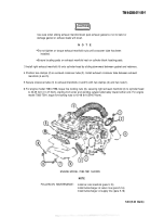
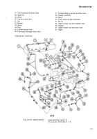
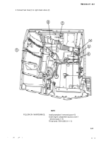
For removal/installation, follow illustration and legend as a guide. During installation, use silicone compound on pipe
threads (only). Secure loop clamp (14) using existing screw on thermostat housing.
LEGEND
1
2
3
4
5
6
7
8
9
10
11
12
13
14
15
16
17
6-2
Upper fuel tank
Upper tank fuel level transmitter
Fuel filler cap gasket*
Fuel tank filler neck and cap
Adapter
Tee
Adapter
Lower fuel tank breather hose
Hose clamp
Upper-to-lower drain tank main drain
Hose flange
Coupling clamp
Elbow
Loop clamp (10)
Engine-to-lower fuel tank hose
(engine model 7083-7396)
Engine-to-lower fuel tank hose
(engine model 7083-7391)
Elbow
18
19
20
21
22
23
24
25
26
27
28
29
30
31
32
33
34
35
36
Adapter
Coupler (male)
Coupler (female)
Adapter
Lower fuel tank return hose
Elbow
Fuel pump
Elbow (2)
Fuel pump
Lower fuel tank
Elbow
Fuel pump discharge check valve
Fuel tank pump hose
Nipple (2)
Personnel heater hose
Screw (1 O)
LockWasher (1 O)*
Screw (4)
LockWasher (4)*
WARNING
INITIAL SETUP
Back to Top

