TM-9-2350-311-20-1 - Page 553 of 1275
TM9-2350-311 -20-1
5-17 ENGINE RIGHT EXHAUST MANIFOLD AND CROSSOVER TUBE — CONTINUED
a. Removal — Continued
1
2
3.
4
5
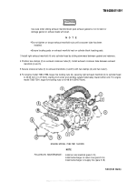
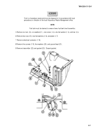
Remove two nuts (1) from two clamps (2) securing exhaust crossover tube (3) to right exhaust manifold (4) and
left exhaust manifold (5). Slide clamps onto manifolds.
Loosen five locking nuts (6), securing right exhaust manifold (4) to side of cylinder head.
Remove exhaust crossover tube (3) from exhaust manifolds (4 and 5). Slide right exhaust manifold (4) upward
and off cylinder head. Remove clamp (2) from manifold.
NOTE
Engine model 7083-7391 has five beveled washers and no end retainers.
Remove five locking nuts (6), three beveled washers (7), and two end retainers (8) from studs (9) on right
cylinder head. Discard locking nuts.
Remove exhaust manifold gasket (1 O). Discard gasket.
b. Installation
Ensure engine and exhaust systems are cool enough to permit handling in order to
prevent bums or injury.
Engine exhaust manifold may slip or fall during installation. Assistance is required
to prevent injury to personnel.
NOTE
Engine model 7083-7391 has an unidirectional exhaust manifold gasket that must be
installed with the mark ‘TOP” facing outward and at the top.
1 Position new gasket (10) over exhaust manifold studs (9) on right cylinder head.
NOTE
Position beveled washers with crown facing nut.
Engine model 7083-7391 has five beveled washers and no end retainers.
2 Install three beveled washers (7), two end retainers (8), and five new locking nuts (6) on right exhaust manifold
studs (9).
5-32
WARNING
Back to Top

