TM-9-2350-311-20-1 - Page 543 of 1275
TM 9-2350-311-20-1
5-11 SOLENOID VALVE AND BRACKET — CONTINUED
Removal — Continued
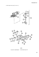
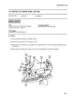
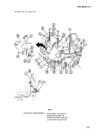
5 Remove two screws (12), two Iockwashers (13), and two washers (14) and disconnect four wiring harness
leads (15 and 16). Discard Iockwashers.
6 Remove two screws (17) and two Iockwashers (18). Discard Iockwashers.
7 Disconnect electrical lead (19).
8 Remove two screws (20), four flat washers (21), and bracket assembly (22) with solenoid valve (5) and
electrical lead (23).
9 Remove two screws (24), two Iockwashers (25), and solenoid valve (5). Discard Iockwashers.
10 Remove four screws (26), four nuts (27), and electrical lead (23).
b. Installation
1
2
3
4
5
6
7
8
9
10
11
12
5-22
Install electrical lead (23) with four nuts (27) and four screws (26).
Secure wiring harness leads (15 and 16) to air inlet housing (28) with two washers (14), two new Iockwashers
(13), and two screws (12). Torque screws to 16-20 Ib-ft (22-27 N•m).
Install solenoid valve (5), two new Iockwashers (25), and two screws (24).
Install hose (1) to connector (3) on solenoid valve (5).
Position solenoid valve (5) with bracket assembly (22) on governor cover (8) inside bracket (29). Loosely
secure solenoid valve and bracket assembly with four washers (21 ) and two screws (20). Do not tighten
screws.
Install two new Iockwashers(18) and two screws (17), securing solenoid valve (5) and bracket assembly (22)
to support bracket (29). Torque screws to 30-35 Ib-ft (41-47 NŽm).
Tighten two screws (20).
Connect electrical lead (19).
Install tee (11 ) into left cylinder head (1 O).
Install connector (9) to tee(11 ).
NOTE
Engine model 7083-7396 does not use clamp (1) on hose (2).
Install hose (2) into connector (9).
Install clamp (1) on hose (2) and secure to governor cover (8) with screw (7).
Back to Top

