TM-9-2350-311-20-1 - Page 535 of 1275
TM 9-2350-311-20-1
5-7 FUEL SHUTOFF ASSEMBLY
This task covers:
a. Removal
b. Installation
T
OO
I
S
Materials/Parts
General mechanic’s tool kit (item 64, Appx H)
Cotter pin (item 37, Appx G)
Lockwashers (3) (item 95, Appx G)
a. Removal
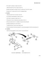
1 Remove quick-release pin (1).
2 Remove cotter pin (2), clevis pin (3), and clevis lever (4). Discard cotter pin.
3 Remove three screws (5) and three Iockwashers (6) at fuel shutoff control assembly (7), located in driver's
compartment. Discard Iockwashers.
4 Remove two screws (8) and pulley bracket (9).
b. Installation
1 Inspect cable for deterioration and inspect pulley for wear and cracks.
2 Install pulley bracket (9) with two screws (8).
3 Install fuel shutoff control assembly (7) in driver’s compartment with three new Iockwashers (6) and three
screws (5).
4 Install clevis lever (4), clevis pin (3), new cotter pin (2), and quick-release pin (1).
5-14
Back to Top

