TM-9-2350-311-20-1 - Page 533 of 1275
TM 9-2350-311-20-1
5-6 SHOCK MOUNT AND BRACKET
This task covers:
a. Removal
b. Installation
INITIAL SETUP
Tools
Equipment Conditions
General mechanic’s tool kit (item 64, Appx H)
Powerplant removed (para 4-5)
Socket wrench set (item 56, Appx H)
Torque wrench (item 72, Appx H)
WARNING
Support powerplant before removing mount to avoid injury to personnel and damage
to powerplant.
a. Removal
NOTE
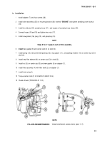
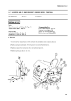
Shock mount and bracket are located on lower rear of engine.
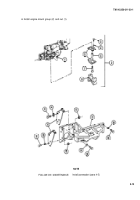
1 Remove nut (1) and engine mount group (2).
2 Remove two screws (3) and two washers (4).
3 Separate two engine shock mount plates (5), spacer (6), and screw (7) from mount (8).
4 Remove eight screws (9), eight flat washers (1 O), eight nuts(11 ), and two support plates (1 2).
5 Remove three screws(13) and three washers (14).
6 Remove eight screws (1 5), eight washers (1 6), and bracket(17) from engine. Inspect mount (8) and bracket for
cracks.
b. Installation
1 Install bracket (17) on engine with eight washers(16) and eight screws (1 5). Torque screws to 60-65 ft-lb (81–
88 N•m).
2 Install three washers (14) and three screws (1 3).
3 Install two support plates(12) with eight flat washers (1 O), eight screws (9), and eight nuts (11).
4 Install mount (8), screw (7), plate (5), spacer (6), and plate (5).
5 Install two washers (4) and two screws (3).
5-12
Back to Top

