TM-9-2350-311-20-1 - Page 530 of 1275
TM 9-2350-311 -20-1
b. Installation
1
2
3
4
5
6
7
8
9
10
11
12
13
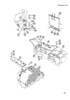
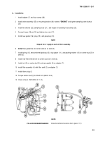
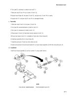
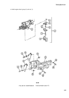
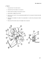
Install adapter (7) and four screws (26).
Install valve assembly (25) on mounting bracket (24) marked
“ENGINE”
and tighten sampling valve locknut
(23).
Install two elbows (22), sampling hose (21 ), and engine oil sampling hose clamp (20).
Connect hoses (18 and 19) and tighten two nuts (17).
Install new gasket (16), plug (15), and pipe plug (14).
NOTE
Steps 6 thru 11 apply to each oil filter assembly.
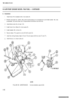
Install
new gasket (8) and center stud (3) on shell (2).
install spring (13), new preformed packing (12), ring spacer (11 ), and packing retainer (10) on center stud (3) in
shell (2).
Install new filter element (9) on center stud (3) in shell (2).
Install nut (5) on center stud (3) and new gasket (6) on adapter (7).
install filter assembly (4) with filter shell (2) on adapter (7).
install drain plug (l).
Torque center stud (3) to 50-60 Ib-ft (68-81 N•m).
Check oil level (TM 9-2350-31 1-10).
FOLLOW-ON MAINTENANCE:
NOTE
Close transmission access doors (para 11-7)
5-9
Back to Top

