TM-9-2350-311-20-1 - Page 615 of 1275
TM9-2350-311-20-1
7-5 SURGE TANK AND PRESSURE RELIEF VALVE
This task covers:
a. Removal
b. Installation
I INITIAL SETUP I
T
OO
I
S
. .
Equipment Conditions
General mechanic’s tool kit (item 64, Appx H)
Air intake grille opened (para 11-8)
Torque wrench (item 72, Appx H)
Coolant system drained (TM 9-2350-311-10)
Engine exhaust deflector removed (para 4-5)
Materials/Parts
Engine exhaust grille removed (para 4-5)
Adhesive (item 1, Appx D)
Grille support plate removed (para 4-5)
Gasket (item 140, Appx G)
Radiator fan access door removed (para 4-5)
Right front grille assembly removed (para 4-5)
Right transmission door removed (para 11-7)
a. Removal
WARNIN G
Ensure engine and coolant system are cool enough to permit safe handling in order to
prevent burns.
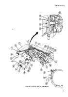
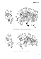
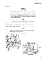
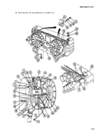
1 Remove two screws (1), two washers (2), and retainer (3).
2 Loosen two clamps (4) at elbow (5).
3 Loosen two clamps (6 and 7).
4 Unscrew two nuts (8 and 9).
5 Disconnect five hoses (10, 11, 12, 13, and 14) from surge tank (15).
6 Lift surge tank (15) up and out.
NOTE
The location of the pressure relief valve differs between M109A2/M109A3 and
M109A4/M109A5 Howitzers.
7 Unscrew nut (16) and remove hose (17) and elbow (18).
8 Remove four screws (19), relief valve (20), and gasket (21) from block (22). Discard gasket.
7-10
Back to Top


