TM-9-2350-311-20-1 - Page 641 of 1275
TM9-2350-311-20-1
7-9 BYPASS THERMOSTAT AND HOUSING ASSEMBLY
This task covers:
a. Removal
b. Installation
T
OO
I
S
General mechanic’s tool kit (item 64, Appx H)
Handle (item 27, Appx H)
Installer (item 31, Appx H)
Socket adapter (item 2, Appx H)
Socket set (item 55, Appx H)
Torque wrench (item 73, Appx H)
Materials/Parts
Adhesive (item 3, Appx D)
Gasket (item 129, Appx G)
Gasket (item 130, Appx G)
Lockwashers (7) (item 88, Appx G)
Seal (item 132, Appx G)
Sealing compound (item 57, Appx D)
Thermostat (item 136, Appx G)
Equipment Conditions
Coolant system drained (TM 9-2350-311-10)
a. Removal
WARNIN G
Ensure engine and coolant system are cool enough to permit safe handling in order to
prevent burns.
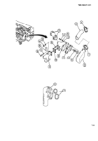
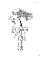
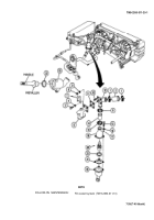
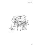
1 Loosen two clamps (1) at crossover tube connector (2).
2 Remove three screws (3), three Iockwashers (4), and gasket (5) at engine coolant manifold (6). Discard
Iockwashers and gasket.
3 Remove protective cover (7) if present.
4 Remove nut (8), Iockwasher (9), and stud (10). Discard Iockwasher.
5 Loosen upper clamp (11).
6 Remove manifold connector (12).
7 Loosen lower clamp (13).
8 Remove coolant hose (14).
9 Remove three screws (15), three Iockwashers (16), and three flat washers (17). Discard Iockwmshers.
10 Separate upper housing (18) and lower housing (19).
11 Remove thermostat (20), gasket (21), and seal (22) by pulling upward. Discard thermostat, gasket, and seal.
7-36
INITIAL SETUP
Back to Top

