TM-9-2350-311-20-1 - Page 649 of 1275
SECTION 1. POWERPLANT ELECTRICAL SYSTEMS
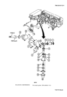
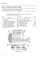
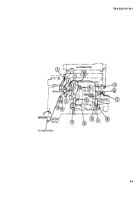
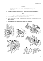
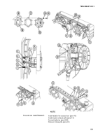
8-1 POWERPLANT ELECTRICAL SYSTEM DIAGRAMS
NOTE
M109A2/M109A3 powerplant electrical system is pictured here. For M109A4/M109A5
powerplant electrical system, see paragraph 8-44.
Connector
Wire Connector
Wire
No.
Electrical Lead To:
No. No.
Electrical Lead To:
No.
1
Aeration detector
352A 11 Air cleaner blower motor switch
415
2
Aeration detector
3526 12 Engine oil pressure transmitter
36
3
Transmission oil temperature transmitter
324 13 Starter motor solenoid from master relay
82
4
Transmission oil high temperature switch
509D 14 Flame heater ignition coil
486
5
Transmission oil low pressure switch
509C 15 Flame heater air pump
486
6
Transmission oil pressure transmitter
321 16 Flame heater solenoid
486A
7
Engine coolant high temperature
509A 17 Fuel prime pump
588
8
Engine coolant temperature transmitter
33A 18 Master circuit harness
12268102
9
Starter motor solenoid from starter relay
146 19 Starter cable connector
82
10 Engine oil low pressure switch
5096
8-4
TM9-2350-311-20-1
Back to Top

