TM-9-2350-311-20-1 - Page 657 of 1275
TM 9-2350-311 -20-1
8-4
RECTIFIER
(M109A2/M109A3)
—
CONTINUED
a. Removal
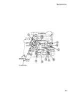
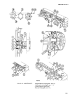
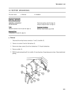
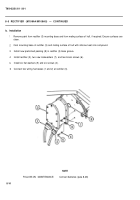
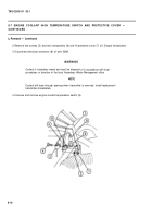
1 Disconnect two wiring harness connectors (1 and 2) at rectifier (3).
2 Remove four screws (4) and four flat washers (5).
3 Remove two brass screws (6) and two lockwashers (7). Discard lockwashers.
4 Remove rectifier (3).
5 Remove preformed packing (8) from rectifier (3) base. Scrape base groove clean. Discard preformed packing.
b. Installation
1
2
3
4
5
6
Remove paint from rectifier (3) mounting base and from mating surface of hull, if required. Ensure surfaces are
clean.
Coat mounting base of rectifier (3) and mating surface of hull with silicone compound.
Install new preformed packing (8) in rectifier (3) base groove. Use silicone compound to hold packing.
Install rectifier (3), two new lockwashers (7), and two brass screws (6). Torque screws at 16 lb-ft (22 N·m).
Install four flat washers (5) and four screws (4). Torque screws to 30 Ib-ft (41 N·m).
Connect two wiring harnesses (1 and 2) at rectifier (3).
NOTE
FOLLOW-ON MAINTENANCE:
Connect batteries (para 8-28)
8-12
Back to Top

