TM-9-2350-311-20-1 - Page 662 of 1275
TM 9-2350-311-20-1
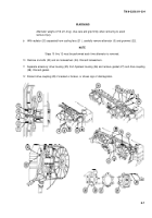
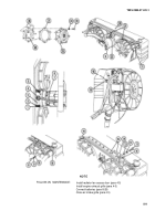
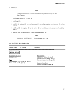
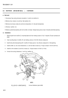
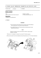
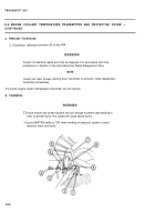
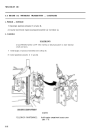
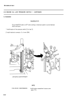
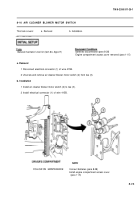
1 Install engine coolant temperature transmitter (9).
2 Connect electrical connector (8) of wire 33A.
3 Install protective cover (7), two new lockwashers (6), and two screws (5).
4 Install clamp (3), screw (4), new lockwasher (2), and nut (1).
NOTE
FOLLOW-ON MAINTENANCE:
Close air intake grille (para 11-8)
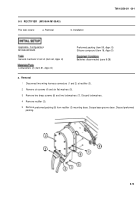
8-7 ENGINE COOLANT HIGH TEMPERATURE SWITCH AND PROTECTIVE COVER
This task covers:
a. Removal
b. Installation
General mechanic’s tool kit (item 64, Appx H)
Lockwashers (3) (item 88, Appx G)
Air intake grille opened (para 11-8)
a. Removal
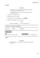
• Ensure engine
prevent bums.
WARNIN G
and coolant system are cool enough to permit safe handling to
Hot coolant will cause severe bums.
• Ensure MASTER switch is OFF when working on electrical system to avoid
electrical shock and burns.
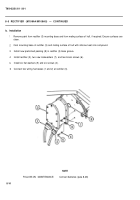
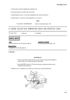
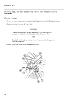
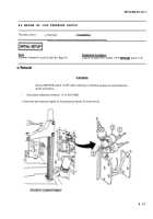
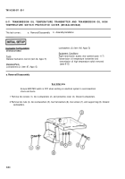
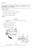
1 Remove nut (1), lockwasher (2), clamp (3), and screw (4). Discard lockwasher.
8-17
Back to Top

