TM-9-2350-311-20-2 - Page 408 of 828
TM 9--2350--311--20--2
7--4
Change 4
7--2
RAMMER ASSEMBLY
This task covers:
a.
Removal
b.
Disassembly
c.
Inspection and Repair
d.
Assembly
e.
Installation
f.
Adjustment
INITIAL SETUP
Tools
Artillery and turret mechanic’s tool kit
(CL 5180--95--A12, see SC 9999--01--SKO)
Torque wrench (item 18, Appx H)
Materials/Parts
Cloth, crocus (item 10, Appx D)
CLP (item 8, Appx D)
Cotter pins (3) (item 37, Appx G)
Cover gasket (item 140, Appx G)
Hydraulic fluid, OHT (item 21, Appx D)
Lockwashers (2) (item 79, Appx G)
Lockwashers (6) (item 81, Appx G)
Lockwashers (7) (item 66, Appx G)
Lockwire (V) (item 106, Appx G)
Lockwire (V) (item 33, Appx G)
Sealing compound (item 29, Appx D)
Spring pin (item 7, Appx G)
Spring pin (item 16, Appx G)
Spring pins (2) (item 13, Appx G)
Personnel Required
2
Equipment Condition
Set cannon at 0
°
elevation
Discharge hydraulic pressure (para 6--3)
Remove rammer lines and fittings (para 7--1)
References
TM 9--2350--311--10
a. Removal
1
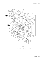
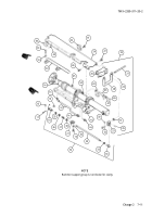
Remove four hex nuts (1), four cap screws (2), four lockwashers (3), and blocking check valve (4). Discard
lockwashers.
2
Move rammer assembly (5) to ram position.
3
Remove lockwire (6), two cap screws (7), and rammer mounting bracket (8). Discard lockwire.
4
Remove lockwire (9), two cap screws (10), two lockwashers (11), two flat washers (11.1), and angle bracket
(12). Discard lockwashers and lockwire.
Back to Top


