TM-9-2350-311-20-2 - Page 412 of 828
TM 9--2350--311--20--2
7--8
Change 4
7--2
RAMMER ASSEMBLY — CONTINUED
b. Disassembly — Continued
15
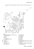
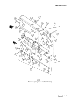
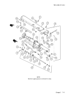
Remove five machine screws (51), five flat washers (52), and cover (53) from rammer support group (54).
16
Remove spring pin (55) and discard.
17
Remove cotter pin (56), flat washer (57), straight headed pin (58), and actuating lever (59). Discard cotter
pin.
18
Remove shoulder pin (60), dial pointer (61), helical compression spring (62), flat washer (63), and actuator
(64).
19
Remove seven machine screws (65), seven lockwashers (66), cover (67), and cover gasket (68) from ram-
mer support group (54). Discard cover gasket, and lockwashers.
20
Remove lockwire (69), two cap screws (70), two lockwashers (71), two flat washers (72), and bridge clamp
(73) from cover (67). Discard lockwire and lockwashers.
Back to Top

