TM-9-2350-311-20-2 - Page 418 of 828
TM 9--2350--311--20--2
7--12
Change 4
7--2
RAMMER ASSEMBLY — CONTINUED
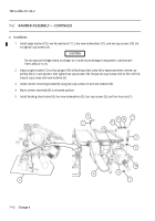
e. Installation
1
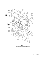
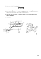
Install angle bracket (12), two flat washers (11.1), two new lockwashers (11), and two cap screws (10). Do
not tighten cap screws yet.
CAUTION
Do not spot paint bridge clamp or plunger as it could cause damage to equipment. Lubricate per
TM 9--2350--311--10.
2
Adjust angle bracket (12) so that plunger (74) of blocking check valve (4) is depressed when rammer as-
sembly (5) is in ram position, then tighten two cap screws (10). Torque two cap screws (10) to 35 to 45 ft-lb.
Secure cap screws with new lockwire (9).
3
Install rammer mounting bracket (8) using two cap screws (7) and new lockwire (6).
4
Move rammer assembly (5) to retracted position.
5
Install blocking check valve (4), four new lockwashers (3), four cap screws (2), and four hex nuts (1).
6
7
9
10
11
2
3
1
8
4
5
12
74
11.1
Back to Top

