TM-9-2350-311-20-2 - Page 422 of 828
TM 9–2350–311–20–2
7–16
Change 3
7–3
RAMMER RELIABILITY CHECKS — CONTINUED
b.
Inspection
CAUTION
•
Do not paint plunger or bridge clamp on rammer valve as it could cause damage to equipment.
Lubricate per TM 9–2350–311–10.
•
Make sure that rammer actuating lever is in inactive (out) position before placing rammer as-
sembly in upright position to avoid damage to equipment.
1
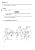
Set the rammer in ram position.
2
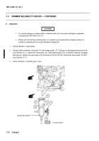
Visually check alinement of plunger (10) with bridge clamp (11). If plunger is disengaged remove and dis-
card lockwire (11.1), loosen two cap screws (12). Slide angle bracket (13) in direction required to engage
with plunger. Tighten two cap screws (12) and torque to 35 to 45 ft-lbs. Secure two cap screws (12) with
new lockwire (11.1).
3
Check operation of rammer (para 7–3a.).
BLOCKING VALVE
12
13
12
DO NOT PAINT
11
10
11.1
Back to Top


