TM-9-2350-311-20-2 - Page 426 of 828
TM 9–2350–311–20–2
8–2
Section I.
ELECTRICAL LEADS AND HARNESSES
8–1
WIRING HARNESS AND CABLE REPAIR
This task covers:
This task covers disassembly and assembly of the following:
a.
Cable, Wire, Receptacle and Plug Identifiers
b.
Female-Type Panel Mounting Receptacle
c.
Male-Type Panel Mounting Receptacle
d.
Female-Type Panel Mounting Receptacle with Ridged Locking Nut
e.
Male-Type Panel Mounting Receptacle with Ridged Locking Nut
f.
Female-Type Plug with Ridged Locking Nut
g.
Male-Type Plug with Ridged Locking Nut
h.
Terminal-Type Cable Connector
i.
Female-Type Cable Connector with Washer
j.
Male-Type Cable Connector with Washer
k.
Female-Type Cable Connector with Sleeve
INITIAL SETUP
Tools
Artillery and turret mechanic’s tool kit
Electrical connector tool kit (item 14, Appx H)
Soldering gun (item 12, Appx H)
Soldering torch kit (item 13, Appx H)
Materials/Parts
Electrical connectors
Flux (item 15, Appx D)
Rosin core solder (item 34, Appx D)
Tag, marking (item 36, Appx D)
Tape, black (electrical) (item 39, Appx D)
Equipment Condition
Disconnect batteries (TM 9–2350–311–10)
WARNING
Disconnect battery ground cable at battery terminal when working on any harness in this section.
Serious burns and electrical shock can result from failure to disconnect battery ground cable.
NOTE
When removing more than one wire from a multiple wire receptacle, record which line was removed
from which pin hole.
a.
Cable, Wire, Receptacle and Plug Identifiers
NOTE
Before proceeding, see instructions on using soldering gun and soldering torch kit (para 2–16).
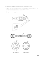
1
Cable identifiers (1) are aluminum tags attached to cables. These tags are embossed with the cable identifi-
cation number. Cable identifier numbers are shown on the system’s wiring diagram.
2
Wire identifiers (2) are embossed with the same individual wire number. Wire identifier numbers are also
shown on system’s wiring diagram.
Back to Top


