TM-9-2350-311-20-2 - Page 532 of 828
TM 9–2350–311–20–2
11–6
11–1 TURRET LOCK ASSEMBLY — CONTINUED
c.
Assembly — Continued
4
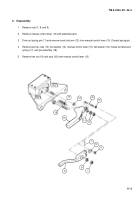
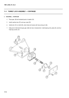
Place gear (28) with attached parts in bracket (24).
5
Install machine key (30) and cap screw (29).
6
Install cam (27) on shaft (25), aline holes and secure with new spring pin (26).
7
Slide end of shaft (25) through gear (28) into hole in bracket (24). Install bearing (23), plate (22), and four
head cap screws (21).
24
29
30
28
23
25
26
22
21
27
Back to Top


