TM-9-2350-311-20-2 - Page 533 of 828
TM 9–2350–311–20–2
11–7
8
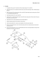
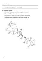
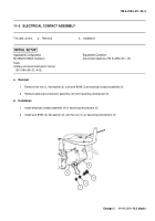
Install stud (20) onto manual control lever (15), then thread hex nut (19) onto stud (20).
9
Install pin assembly (18), helical compression spring (17), flat washer (16), manual control lever (15), flat
washer (14), and two hex nuts (13).
10
Position turret lock arm (12) in clevis of manual control lever (10), aline holes and drive in new spring pin
(11) to secure turret lock arm. Make sure turret lock arm is free to pivot in clevis.
11
Slide end of manual control lever (10) into slot in manual control lever (15). End of stud (20) must protrude
from hole in turret lock arm (12). Install nut (9) on stud (20).
12
Install nuts (7 and 8) on pin assembly (18).
8
7
11
17
19
18
15
14
13
12
9
16
20
10
Back to Top


