TM-9-2350-311-20-2 - Page 534 of 828
TM 9–2350–311–20–2
11–8
Change 3
11–1 TURRET LOCK ASSEMBLY — CONTINUED
d.
Installation
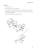
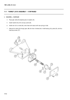
1
Install turret lock assembly (6) and secure using two cap screws (5), new shims (4), two new lockwashers
(3), two flat washers (2), and two new self-locking bolts (1). Machine key (30) fits into hole (40) in geared
race (41) to locate turret lock assembly (6) properly. Torque cap screws to 248-302 lb-ft.
2
Move manual control lever (15) to LOCKED position and check to be sure that teeth of gear (28) engage
teeth of geared race (41) and that pin assembly (18) engages hole in turret lock assembly (6) for LOCKED
position.
3
Vary thickness of shims (35) to adjust engagement of gear (28) with teeth of geared race (41). Decreasing
thickness of shims brings gear into closer engagement with race; increasing shims thickness moves gear
away from race. Shims are available in three thicknesses: 0.001, 0.002, and 0.003 inches (0.03, 0.05, and
0.08 mm).
41
40
4
3
2
1
1
5
6
15
30
18
35
28
6
Back to Top


