TM-9-2350-311-20-2 - Page 543 of 828
TM 9–2350–311–20–2
12–3
c.
Assembly
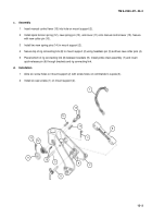
1
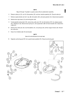
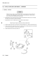
Insert manual control lever (15) into hole on mount support (2).
2
Install spiral torsion spring (12), new spring pin (13), and cover (11) onto manual control lever (15). Secure
with new cotter pin (10).
3
Install two new spring pins (14) in mount support (2).
4
Secure top of rig connecting link (8) to mount support (2) using headless pin (5) and two new cotter pins (4).
5
Place bottom of rig connecting link (8) between brackets (9). Install pintle chain assembly (7) and insert
quick-release pin (6) through brackets and rig connecting link.
d.
Installation
1
Aline six screw holes on mount support (2) with screw holes on commander’s cupola (3).
2
Install six cap screws (1) on mount support (2).
12
10
11
13
5
9
2
6
7
4
8
14
15
14
Back to Top


