TM-9-2350-311-20-2 - Page 550 of 828
TM 9–2350–311–20–2
12–8
12–3 CUPOLA COVER, BODY, AND HANDLE — CONTINUED
b.
Disassembly — Continued
NOTE
Steps 13 through 17 pertain to cupola covers with outside latch handle.
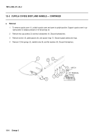
13
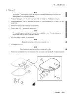
Remove shoe assembly (47), screw assembly (48), flat washer (49), and helical compression spring (50)
from cupola body assembly (46).
14
Remove two cap screws (51), cupola cover block (52), and plate spacers (53) from cupola body assembly
(46). Discard plate spacers.
15
Remove self-locking nuts (54), flat washer (55), sleeve bearing (56), and door handle (57) from cupola cover
(1). Discard self-locking nuts.
16
Remove two cap screws (58) and block latch lock (59) from cupola cover (1).
17
Remove two machine bolts (60), two lockwashers (61), and flat spring (62) from block latch lock (59). Dis-
card lockwashers.
c.
Assembly
NOTE
Steps 1 through 5 pertain to cupola covers with outside latch handle.
1
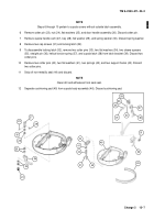
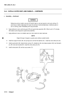
Secure flat spring (62) to block latch lock (59) using two new lockwashers (61) and two machine bolts (60).
2
Secure block latch lock (59) to cupola cover (1) using two cap screws (58).
3
Install sleeve bearing (56), door handle (57), flat washer (55), and new self-locking nut (54) to cupola cover
(1).
4
Secure new plate spacer (53), cupola cover block (52), and two cap screws (51) to cupola body assembly
(46).
5
Install helical compression spring (50), flat washer (49), screw assembly (48), and shoe assembly (47).
Back to Top


