TM-9-2350-311-20-2 - Page 556 of 828
TM 9–2350–311–20–2
12–14
Change 2
12–3 CUPOLA COVER, BODY, AND HANDLE — CONTINUED
e.
Adjustment
1
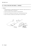
To adjust anchor/torsion bar assembly on cupola cover (1), insert new spacer plate(s) (6) as required. Pro-
vide a 0.016 + 0.063 inch (0.406 + 1.6 mm) clearance between spring ends and anchor.
2
Insert new spacer ring(s) (7) as required. Provide a 0.005 + 0.200 inch (0.127 + 5.08 mm) clearance be-
tween tube end and cover hinge.
3
Insert new flat washer(s) (9) as required. Center hatch in cupola body within 0.047 inch (1.2 mm).
4
Insert new flat washers(s) (25) as required. Provide spring washer (30) depression of approximately 0.031
inch (0.79 mm) in UNLOCK position.
NOTE
Step 5 pertains to commander’s cupola assemblies which have been modified and use the knob
latch assembly.
5
To adjust catch/latch assembly on cupola cover (1) when secured in open position, insert shims (11.4) as
required. Provide a 0.06 to 0.12 inch (1.524 to 3.048 mm) clearance between end of plunger of latch assem-
bly (22.4) and to back of slot in catch (11.3).
1
6
7
9
30
25
11.4
11.3
1
22.4
Back to Top

