TM-9-2350-311-20-2 - Page 564 of 828
TM 9–2350–311–20–2
13–8
13–3 SEAT ADJUSTER ASSEMBLY
This task covers:
a.
Disassembly
b.
Assembly
INITIAL SETUP
Tools
Artillery and turret mechanic’s tool kit
(SC 5180–95–CL–A12)
a.
Disassembly
1
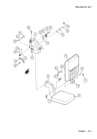
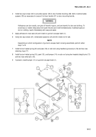
Remove permanent washer (1), headless shoulder pin (2), and two rollers (3) from seat carriage (4).
2
Remove headed grooved pin (5) from manual control handle (6) on seat carriage (4).
3
Remove headless grooved pin (7) from rod end clevis (8). This will release manual control handle (6) along
with flat washer (9), spring (10), and sleeve bushing (11).
b.
Assembly
1
Install sleeve bushing (11), spring (10), flat washer (9), and manual control handle (6). Install headless
grooved pin (7) in rod end clevis (8).
2
Position manual control handle (6) on seat carriage (4) and install headed grooved pin (5).
3
Install two rollers (3), headless shoulder pin (2), and permanent washer (1) on seat carriage (4).
2
1
3
4
9
11
7
8
5
10
6
Back to Top


