TM-9-2350-311-20-2 - Page 568 of 828
TM 9–2350–311–20–2
14–4
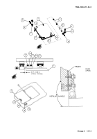
14–1 GUNNER’S ESCAPE HATCH (UNMODIFIED) — CONTINUED
b.
Disassembly
NOTE
Some vehicles do not have bumper.
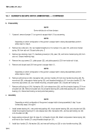
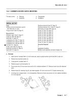
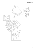
1
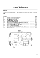
If present, remove bumper (11) on gunner’s escape hatch (1) by unscrewing.
NOTE
Depending on which configuration of the gunner’s escape hatch is being disassembled, perform
either step 2 or step 3.
2
Remove two cotter pins (12), two headed straight pins (13), bumper (14), pawl (15), and torsion helical
spring (16) from cab roof. Discard cotter pins. 2
3
Remove two retaining rings (17), headless grooved pin (18), pawl (19), and torsion helical spring (20) from
cab roof. Discard retaining rings.
4
Remove two cap screws (21), plate spacer (22), and plate spacer(s) (23) from inside roof of cab.
5
Remove and discard seal (24) from gunner’s escape hatch (1).
NOTE
Depending on which configuration of the gunner’s escape hatch is being disassembled, perform
either step 6 or step 7.
6
Remove self-locking nut (25), flat washer (26), and door handle (27) from door handle mounting (28). Re-
move knob (29), compression helical spring (30), and threaded straight pin (31) from door handle (27). Re-
move two cap screws (32), door handle mounting, and plate spacer (33). Discard self-locking nut.
7
Remove self-locking nut (34), flat washer (35), lock-release lever (36), and thrust washer bearing (37) from
shoulder bolt (38). Remove shoulder bolt, thrust washer bearing (39), preformed packing (40), and sleeve
bearing (41). Discard self-locking nut and preformed packing.
c.
Assembly
NOTE
Depending on which configuration of the gunner’s escape hatch is being assembled, if step 1 is per-
formed skip steps 2 through 4.
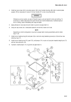
1
Install sleeve bearing (41), new preformed packing (40), thrust washer bearing (39), and shoulder bolt (38).
Install thrust washer bearing (37), lock-release lever (36), flat washer (35), and new self-locking nut (34)
onto shoulder bolt (38).
2
Apply sealing compound (item 30, Appx D), to threads of knob (29). Attach compression helical spring (30)
and knob to door handle (27) using threaded straight pin (31).
3
Install door handle (27), flat washer (26), and new self-locking nut (25) on door handle mounting (28).
Back to Top


