TM-9-2350-311-20-2 - Page 571 of 828
TM 9–2350–311–20–2
Change 3
14–7
14–2 GUNNER’S ESCAPE HATCH (MODIFIED)
This task covers:
a.
Removal
b.
Disassembly
c.
Assembly
d.
Installation
INITIAL SETUP
Tools
Artillery and turret mechanic’s tool kit
(SC 5180–95–CL–A12)
Torque wrench (item 18, Appx H)
Materials/Parts
Adhesive, type I (item 2, Appx D)
Cotter pin (item 38, Appx G)
GAA (item 17, Appx D)
Lockwashers (4) (item 77, Appx G)
Lockwashers (6) (item 81, Appx G)
Lockwashers (2) (item 83, Appx G)
Pin (item 10.1, Appx G)
Primer, paint (item 24, Appx D)
Retaining ring (item 20, Appx G)
Seal (item 110, Appx G)
Sealing compound (item 30, Appx D)
Sealing compound, No. 2 (item 27, Appx D)
Self-locking nut (item 185, Appx G)
Shims (V) (item 143, Appx G)
Shims (V) (item 144, Appx G)
Shims (V) (item 145, Appx G)
Shims (V) (item 146, Appx G)
Shims (V) (item 147, Appx G)
Shims (V) (item 148, Appx G)
Shims (V) (item 149, Appx G)
Shims (V) (item 150, Appx G)
Personnel Required
2
Equipment Condition
Ballistic cover assembly removed (Chapter 16)
a.
Removal
1
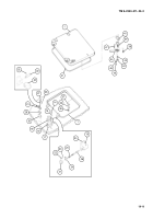
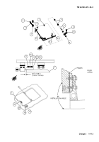
Open gunner’s escape hatch (1) from inside cab, raise to upright position and hold at 90
°
to cab roof.
2
Remove two machine screws (2).
3
Close gunner’s escape hatch (1).
4
Remove plug (3) and flat washer (4).
5
Drive torsion bar (5) from torsion bar anchor (6) in retainer weldment (7). Remove torsion bar with attached
parts.
6
Remove tube (8), retaining ring (9), and retaining plate (10) from torsion bar (5). Discard retaining ring.
7
Lift off gunner’s escape hatch (1) for disassembly. Removal of torsion bar anchor (6) from retainer weldment
(7) is not required.
9
10
2
5
8
3
7
6
4
1
Back to Top

