TM-9-2350-311-20-2 - Page 578 of 828
TM 9–2350–311–20–2
14–14
14–3 LATCH ASSEMBLY, SIDE DOORS
This task covers:
a.
Removal
b.
Disassembly
c.
Assembly
d.
Installation
INITIAL SETUP
Tools
Artillery and turret mechanic’s tool kit
(SC 5180–95–CL–A12)
Materials/Parts
GAA (item 17, Appx D)
Lockwashers (4) (item 77, Appx G)
Lockwashers (8) (item 81, Appx G)
Sealing compound (item 32, Appx D)
Shims (V) (item 143, Appx G)
Shims (V) (item 144, Appx G)
Shims (V) (item 145, Appx G)
Shims (V) (item 146, Appx G)
NOTE
This procedure is written for one latch assembly, but applies to both latch assemblies.
a.
Removal
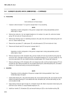
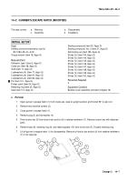
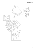
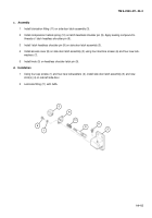
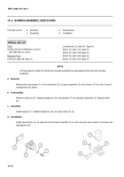
Remove four cap screws (1), four lockwashers (2), side door latch assembly (3) and shim(s) (4) from cab left
side door. Discard lockwashers and shims.
b.
Disassembly
1
Remove knob (5).
2
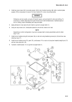
Remove four machine screws (6), four lockwashers (7), and access cover (8). Discard lockwashers.
3
Pull out latch headless shoulder pin (9) and compression helical spring (10).
4
Remove lubrication fitting (11) and discard if damaged.
4
3
2
1
Back to Top

