TM-9-2350-311-20-2 - Page 576 of 828
TM 9–2350–311–20–2
14–12
Change 3
14–2 GUNNER’S ESCAPE HATCH (MODIFIED) — CONTINUED
d.
Installation
NOTE
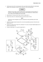
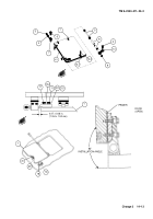
Immediately prior to installation, apply primer to all contact surfaces, except threaded ones, as
shown in illustration.
1
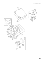
Place gunner’s escape hatch (1) with new seal (41) in cab roof.
2
Place torsion bar anchor (6) in retainer weldment (7), if it has been removed.
3
Install retaining plate (10) and new retaining ring (9) on one end of torsion bar (5).
4
Install tube (8) over torsion bar (5) and then insert as an assembly through hinges of gunner’s escape hatch
(1) and roof, but do not engage splines on end of torsion bar with torsion bar anchor (6).
5
Install two machine screws (2) to fasten retaining plate (10) to gunner’s escape hatch (1).
6
Raise gunner’s escape hatch (1) to approximately 83
°
from the horizontal (closed) position (refer to illustra-
tion) and engage torsion bar splines with internal splines of torsion bar anchor (6). It is better to engage the
torsion bar (5) at less then 83
°
, rather than more, if an exact installation is not possible. (A change of one
spline equals approximately 28
°
.)
7
Apply sealing compound (item 30, Appx D) to plug (3). Install flat washer (4) and plug. Torque plug to 50 lb–
ft (37 N
.
m).
7.1
Open gunner’s escape hatch (1) ensuring latch assembly (18) is engaged. Measure overlap of headless
shoulder pin (26) on the catch strike (13) or slotted catch strike (12.1). Measurement should be 0.47
±
0.06
in. (11.94
±
1.52 mm), if this measurement is not achieved, replace catch strike (13) with slotted catch strike
(12.1) or perform Step 7.2 to adjust slotted catch strike.
7.2
Remove pin (12.2) from a new slotted catch strike (12.1) if installed. Loosen two cap screws (11) and adjust
slotted catch strike until measurement of 0.47
0.06 in. (11.94
1.52 mm) is achieved. Tighten two cap
screws. Drill a 0.125 + 0.004 in. (3.18 + 0.102 mm) dia hole 0.38 in. (9.65 mm) deep into the gunner’s es-
cape hatch (1) using the slotted catch strike as a guide. Reinstall pin or install new pin (12.2) to secure.
8
Check that latch assembly (18) firmly secures gunner’s escape hatch (1) against bumper assembly (31).
Adjust shims (16) of latch assembly and shims (29) of bumper assembly if necessary.
9
Close gunner’s escape hatch (1) to check seal integrity and operation of latch.
Back to Top

