TM-9-2350-311-20-2 - Page 567 of 828
TM 9–2350–311–20–2
14–3
14–1 GUNNER’S ESCAPE HATCH (UNMODIFIED)
This task covers:
a.
Removal
b.
Disassembly
c.
Assembly
d.
Installation
INITIAL SETUP
Tools
Artillery and turret mechanic’s tool kit
(SC 5180–95–CL–A12)
Torque wrench (item 18, Appx H)
Materials/Parts
Adhesive, type I (item 2, Appx D)
Cotter pins (2) (item 38, Appx G)
Seal (item 110, Appx G)
Sealing compound (item 30, Appx D)
Sealing compound, No. 2 (item 27, Appx D)
Preformed packing (item 50, Appx G)
Primer, paint (item 24, Appx D)
Retaining ring (item 20, Appx G)
Retaining rings (2) (item 21, Appx G)
Self-locking nut (item 185, Appx G)
Self-locking nut (item 35, Appx G)
Personnel Required
2
a.
Removal
1
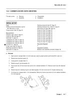
Open gunner’s escape hatch (1) from inside cab, raise to upright position and hold at 90
°
to cab roof.
2
Remove two machine screws (2).
3
Close gunner’s escape hatch (1).
4
Remove plug (3) and flat washer (4).
5
Drive torsion bar (5) from torsion bar anchor (6) in retainer weldment (7). Remove torsion bar with attached
parts.
6
Remove tube (8), retaining ring (9), and retaining plate (10) from torsion bar (5). Discard retaining ring.
7
Lift off gunner’s escape hatch (1) for disassembly. Removal of torsion bar anchor (6) from retainer weldment
(7) is not required.
1
9
10
2
5
8
7
4
3
6
Back to Top

