TM-9-2350-311-20-2 - Page 572 of 828
TM 9–2350–311–20–2
14–8
Change 3
14–2 GUNNER’S ESCAPE HATCH (MODIFIED) — CONTINUED
b.
Disassembly
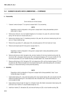
NOTE
Step 1 applies only to vehicles with slotted catch strike.
1
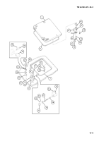
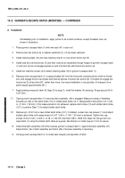
Remove two cap screws (11), two lockwashers (12), slotted catch strike (12.1) and pin (12.2). Discard pin
and lockwashers.
2
Remove two cap screws (11), two lockwashers (12), and catch strike (13). Discard lockwashers.
3
Remove four cap screws (14), four lockwashers (15), shim(s) (16), latch block (17), and latch assembly (18).
Discard lockwashers and shims.
4
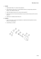
Disassemble latch assembly (18) if necessary:
(a)
Remove lubrication fitting (19) from latch body (20) and remove knob (21).
(b)
Remove four machine screws (22), four lockwashers (23), access cover (24), compression helical
spring (25), and headless shoulder pin (26), from latch body (20). Discard lockwashers.
5
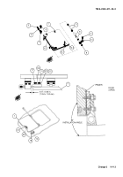
Remove two cap screws (27), two lockwashers (28), shim(s) (29), bumper block (30), and bumper assembly
(31). Discard lockwashers and shims.
6
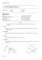
Disassemble bumper assembly (31), if necessary, by removing cotter pin (32), headed straight pin (33), and
bumper (34). Discard cotter pin.
7
Remove two cap screws (35), plate spacer (36), and plate spacer(s) (37) from inside roof of cab.
8
Remove two cap screws (38), joining door handle mounting (39) to plate spacer (40).
9
Remove and discard seal (41) from gunner’s escape hatch (1).
10
Remove self-locking nut (42), flat washer (43), and door handle (44) from door handle mounting (39). Dis-
card self-locking nut.
11
Remove knob (45), compression helical spring (46), and threaded straight pin (47) from door handle (44).
11
13
12
1
11
12
12.1
12.2
Back to Top


