TM-9-2350-311-20-2 - Page 581 of 828
TM 9–2350–311–20–2
Change 3
14–17
14–5 CAB SIDE DOORS, LEFT AND RIGHT
This task covers:
a.
Removal
b.
Disassembly
c.
Assembly
d.
Installation
INITIAL SETUP
Tools
Artillery and turret mechanic’s tool kit
(SC 4933–95–A12)
Materials/Parts
Adhesive, type I (item 2, Appx D)
Lockwashers (2) (item 83, Appx G)
Pin (item 10.1, Appx G)
Plate spacers (V) (item 136, Appx G)
Seal (item 118, Appx G)
Sealing compound (item 30, Appx D)
Self-locking nut (item 185, Appx G)
Spring pin (item 11, Appx G)
Strip (item 172.2, Appx G)
Zinc chromate paste (item 23, Appx D)
Personnel Required
2
NOTE
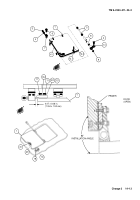
This procedure is written for the left cab side door, but also applies to the right cab side door.
a.
Removal
1
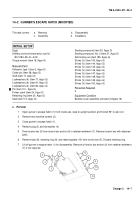
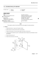
Hold left cab side door (1) open at a 90
°
angle for removal.
2
Remove spring pin (2) from torsion bar anchor (3) and discard.
3
Remove two cap screws (4) from torsion bar bracket (5) at bottom of torsion bar (6).
4
To remove torsion bar bracket (5), tube (7), and flat washer(s) (8) from hinges (9), pull downward on torsion
bar bracket (5).
5
Remove left cab side door (1).
6
Remove torsion bar anchor (3) from cab.
4
5
6
8
8
2
3
1
7
9
9
Back to Top

