TM-9-2350-311-20-2 - Page 590 of 828
TM 9–2350–311–20–2
14–26
14–8 BUSTLE DOOR ASSEMBLIES, LEFT AND RIGHT
This task covers:
a.
Removal
b.
Disassembly
c.
Assembly
d.
Installation
INITIAL SETUP
Tools
Artillery and turret mechanic’s tool kit
(SC 5180–95–CL–A12)
Materials/Parts
Adhesive, type I (item 2, Appx D)
Cushioning pad (item 154, Appx G)
Cushioning pad (item 158, Appx G)
Lockwashers (8) (item 83, Appx G)
Rubber strips (2) (item 153, Appx G)
Rubber strips (2) (item 157, Appx G)
Seal (item 155, Appx G)
Seal (item 159, Appx G)
Seals (2) (item 152, Appx G)
Self-locking nut (item 183, Appx G)
Self-locking nuts (2) (item 28, Appx G)
Self-locking nuts (4) (item 186, Appx G)
Shims (V) (item 166, Appx G)
Shims (V) (item 167, Appx G)
Sleeve bearings (8) (item 27, Appx G)
Zinc chromate paste (item 23, Appx D)
Personnel Required
2
Equipment Condition
Projectile access door assembly removed (para 14–7)
a.
Removal
NOTE
Bustle doors may be removed and installed using a sling through the upper locking arm side plate. If
sling and hoist are not available, use two personnel to remove and install doors.
1
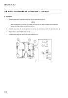
Remove and discard two self-locking nuts (1). Remove two cap screws (2) and four flat washers (3). Unlatch
right bustle door (4). Use two personnel to lift right bustle door out of bustle (5).
2
Repeat step 1 for left bustle door (6).
6
4
5
2
3
3
1
Back to Top

