TM-9-2350-311-20-2 - Page 596 of 828
TM 9–2350–311–20–2
14–32
Change 2
14–10 BUSTLE DOOR WIRE ROPE ASSEMBLIES, LEFT AND RIGHT
This task covers:
a.
Removal
b.
Disassembly
c.
Assembly
d.
Installation
INITIAL SETUP
Tools
Artillery and turret mechanic’s tool kit
(SC 5180–95–CL–A12)
NOTE
Procedures are written for right wire rope assembly, but also apply to the left wire rope assembly.
a.
Removal
1
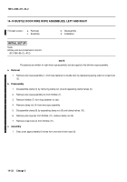
Remove wire rope assembly (1) from loop fastener on bustle door by depressing spring catch on snap hook
(2).
b.
Disassembly
1
Disassemble clamp (3) by removing clamp nut (4) and separating clamp halves (5).
2
Remove wire rope assembly (6) from thimble (7).
3
Remove thimble (7) from loop fastener on cab.
4
Remove clamp nut (4) from wire rope assembly.
5
Disassemble clamp (8) by separating clamp nut (9) and clamp halves (10).
6
Remove wire rope (6) from thimble (11), remove clamp nut (9).
7
Remove snap hook (2) from thimble (11).
c.
Assembly
1
Strip cover approximately 6 inches from one end of wire rope (6).
Back to Top


