TM-9-2350-311-20-2 - Page 605 of 828
TM 9–2350–311–20–2
Change 2
15–3
Section I.
CAB AMMO RACK
15–1 RETAINER ASSEMBLY
This task covers:
a.
Removal
b.
Disassembly
c.
Assembly
d.
Installation
INITIAL SETUP
Tools
Artillery and turret mechanic’s tool kit
(SC 5180–95–CL–A12)
Materials/Parts
Sealing compound (item 28.2, Appx D)
Self-locking screws (4) (item 21.2, Appx G)
Self-locking screws (4) (item 23, Appx G)
Serrated lock rings (4) (item 100, Appx G)
Spring pin (item 11.3, Appx G)
Wire swaging sleeves (2) (item 134, Appx G)
a.
Removal
NOTE
•
There are 22 retainer assemblies in the cab ammo rack, but procedures apply to only one. Re-
move only those retainers which require repair or replacement.
•
Each retainer assembly is held in place by two locking caps. For posts not on the perimeter of
the rack, the locking caps have an irregular shape somewhat like a triangle.
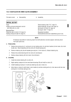
1
Remove two shoulder screws (1), two locking caps (2 or 3), and two quick-release plungers (4) from two
posts (5).
2
Remove machine bolt (6) from post (5) to release wire rope (7). Machine bolt will still be attached to wire
rope.
3
Remove retainer assembly (8) from projectile stowage rack assembly (9).
1
5
2
7
6
4
1
3
4
8
9
5
Back to Top

