TM-9-2350-311-20-2 - Page 606 of 828
TM 9–2350–311–20–2
15–4
Change 2
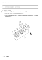
15–1 RETAINER ASSEMBLY — CONTINUED
b.
Disassembly
NOTE
•
Refer to steps 1 through 4 to disassemble retainer assembly PN 11828875.
•
Refer to steps 5 through 10 to disassemble retainer assembly PN 12940880.
1
Remove two wire swaging sleeves (10) from ends of wire rope (7). This will release machine bolt (6) and
retainer assembly (8) from end of wire rope. Discard wire swaging sleeves. Replace wire rope if frayed or
broken.
2
Remove four self-locking screws (11) from retainer assembly (8). Discard self-locking screws.
3
Remove access cover (12), rubber bushing (13), and four serrated lock rings (14), from retainer body as-
sembly (15). Discard serrated lock rings.
4
If necessary for replacement, remove decals (16, 17, and 18).
8
15
14
10
12
13
8
7
10
6
9
7
11
10
5
16
17
18
Back to Top

