TM-9-2350-311-20-2 - Page 585 of 828
TM 9–2350–311–20–2
14–21
14–6 CAB BUSTLE DOOR GROUP (STRIKE AND BRACKET ASSEMBLIES)
This task covers:
a.
Removal
b.
Installation
INITIAL SETUP
Tools
Artillery and turret mechanic’s tool kit
(SC 5180–95–CL–A12)
Materials/Parts
Cotter pins (2) (item 38, Appx G)
Lockwashers (8) (item 81, Appx G)
Lockwashers (6) (item 83, Appx G)
Shims (V) (item 163, Appx G)
Shims (V) (item 164, Appx G)
Shims (V) (item 165, Appx G)
Personnel Required
2
a.
Removal
NOTE
•
Inspect inserts in screw and bolt holes. If threads are stripped or damaged, replace inserts.
•
Bustle doors must be open or removed (para 14–8), for removal of strike assemblies.
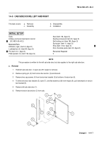
1
Remove six cap screws (1), six lockwashers (2), and two strike assemblies (3) from top of bustle door as-
semblies (left and right) (4). Discard lockwashers.
2
Remove four cap screws (5), shim(s) (6) (if used), and two strike assemblies (7) from bottom of
bustle door
assemblies (left and right) (4). Discard shims.
1
2
3
4
6
7
5
Back to Top


