TM-9-2350-311-20-2 - Page 579 of 828
TM 9–2350–311–20–2
14–15
c.
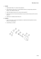
Assembly
1
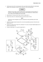
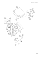
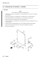
Install lubrication fitting (11) on side door latch assembly (3).
2
Install compression helical spring (10) on latch headless shoulder pin (9). Apply sealing compound to
threads of
latch headless shoulder pin (9).
3
Install
latch headless shoulder pin (9) on side door latch assembly (3).
4
Install access cover (8) on side door latch assembly (3) using four machine screws (6) and four new lock-
washers (7).
5
Install knob (5) on headless shoulder latch pin (9).
d.
Installation
1
Using four cap screws (1) and four new lockwashers (2), install side door latch assembly (3) and new
shim(s) (4) on cab left side door.
2
Lubricate fitting (11) with GAA.
6
7
5
8
10
9
11
3
Back to Top

