TM-9-2350-311-20-2 - Page 584 of 828
TM 9–2350–311–20–2
14–20
Change 3
14–5 CAB SIDE DOORS, LEFT AND RIGHT — CONTINUED
d.
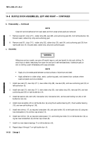
Installation
1
Install torsion bar anchor (3) into cab. Be sure holes for spring pin (2) are horizontal.
2
Place left cab side door (1) over seal in door opening, alining holes in hinges (9), and support door assembly
in this position.
3
Install flat washers (8), as required, torsion bar (6), and tube (7) in hinges (9) of left cab side door (1). Aline
the hole in torsion bar with the hole for spring pin (2) in torsion bar anchor (3).
4
Install new spring pin (2) to retain torsion bar (6) in torsion bar anchor (3).
5
Open left cab side door (1) to 90
°
and support in this position.
6
Install torsion bar bracket (5) by alining with splines of torsion bar (6) and fasten to left cab side door (1) en-
suring left cab side door is perpendicular to the cab.
7
Install torsion bar bracket (5) to left cab side door (1) with two cap screws (4).
7.1
Open left cab side door (1) ensuring latch is engaged. Measure over lap of latch pin on the catch strike. It
should be 0.47
±
0.06 in. (11.94
±
1.52 mm), if this measurement is not achieved, replace catch strike (12)
with slotted catch strike (11.1) or perform Step 7.2 to adjust slotted catch strike.
7.2
Remove pin (11.2) from new slotted catch strike (11.1) if installed. Loosen cap screws (10) and adjust
slotted catch strike until measurement of 0.47
±
0.06 in. (11.94
±
1.52 mm) is achieved. Tighten cap screws
(10). Drill a hole 0.125
±
0.004 in.
(3.18 + 0.102 mm) deep into the cab side door (1) using slotted catch
strike as a guide. Reinstall pin
or install new pin (11.2) to secure.
8
Close left cab side door (1). When latch is released, the left cab side door (1) will spring open gently if prop-
erly installed.
2
3
4
5
6
8
8
1
7
9
9
10
11.2
LATCH PIN
0.47
±
0.06 in.
(11.94
±
1.52 mm)
11.2
11.1
Back to Top

