TM-9-2350-311-20-2 - Page 558 of 828
TM 9–2350–311–20–2
13–2
13–1 COMMANDER’S SEAT AND SUPPORT POST GROUP
This task covers:
a.
Removal
b.
Disassembly
c.
Assembly
d.
Installation
e.
Adjustment
INITIAL SETUP
Tools
Artillery and turret mechanic’s tool kit
(SC 5180–95–CL–A12)
Materials/Parts
Lockwasher (item 84, Appx G)
Lockwashers (4) (item 79, Appx G)
Lockwashers (4) (item 81, Appx G)
a.
Removal
NOTE
Except for adjusting the seat, perform the procedures in this paragraph only if the entire seat needs
repair.
1
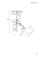
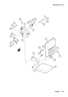
Remove four cap screws (1) four lockwashers (2), and four flat washers (3) from top and bottom of seat sup-
port (4). Entire commander’s seat assembly (5) will now come off. Discard lockwashers.
2
Remove permanent washer (6) and headless shoulder pin (7) from seat carriage (8). This will release seat
(9) and backrest (10) (assembled).
3
Remove hex nut (11), lockwasher (12), flat washer (13), cap screw (14), and two angle brackets (15). Dis-
card lockwasher.
4
Pull manual control handle (16) toward you and slide seat carriage (8) upward to remove from seat support
(4).
Back to Top


