TM-9-2350-311-20-2 - Page 548 of 828
TM 9–2350–311–20–2
12–6.2
Change 2
12–3 CUPOLA COVER, BODY, AND HANDLE — CONTINUED
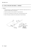
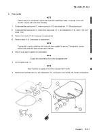
NOTE
Perform step 5 for commander’s cupola with hook latch assembly or steps 5.1 through 5.3 for com-
mander’s cupola with knob latch assembly.
5
To disassemble cupola body, remove two cotter pins (16), two flat washers (17), two sleeve spacers (18),
straight pin (19), spring (20), and manual control lever (21) from latch bracket (22). Discard cotter pins.
5.1
Remove four cap screws (22.1), two cap screws (22.2), six lockwashers (22.3), latch assembly (22.4), and
adapter plate (22.5).
5.2
Remove four inserts (22.6) if necessary for replacement.
5.3
See para 14–3 for disassembly of knob latch assembly (22.4).
21
19
18
17
20
18
17
16
22
22.1
22.3
22.2
22.3
22.6
22.5
22.4
Back to Top


