TM-9-2350-311-20-2 - Page 632 of 828
TM 9–2350–311–20–2
15–26
Change 2
15–12 CANNISTER STOWAGE BRACKET ASSEMBLY — CONTINUED
b.
Installation
NOTE
Apply zinc chromate paste between contact surfaces where aluminum meets steel. Apply sealing
compound to all machine screws before installing.
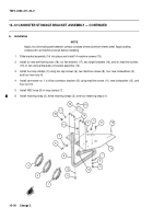
1
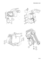
Slide bracket assembly (14) into place and install 14 machine screws (19).
2
Install six new self-locking nuts (18), six flat washers (17), two angle brackets (16), and six machine screws
(15) on two vertical brackets on bracket assembly (14).
3
Install four loop clamps (7) using two cap screws (6), two machine screws (8), four new lockwashers (5),
and four hex nuts (4).
4
Install cannoneer no. 1’s orifice connector bracket (13) using machine screw (11), new lockwasher (12), and
hex nut (10).
5
Install NBC hose (9) in loop clamps (7).
6
Install retaining strap (3), three retaining straps (2), and four retaining straps (1).
Back to Top


