TM-9-2350-311-20-2 - Page 666 of 828
TM 9–2350–311–20–2
17–28
Change 2
17–6 AIR OUTLET ORIFICE CONNECTOR
This task covers:
a.
Removal
b.
Installation
INITIAL SETUP
Applicable Configuration
M109A4/M109A5 howitzers
Tools
Artillery and turret mechanic’s tool kit
(SC 5180–95–CL–A12)
Materials/Parts
Lockwasher (item 79, Appx G)
a.
Removal
NOTE
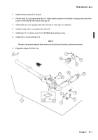
This procedure is written for one air outlet orifice connector, but applies to all.
1
Remove hose clamp (1) and hose (2) from coupling (3).
2
Remove coupling (3).
NOTE
Because of inadequate clearance between angle bracket and cab wall at gunner’s station, perform
step (4) before step (3) to remove and replace gunner’s orifice connector.
3
Remove retaining ring (4) and orifice connector (5).
NOTE
Machine screw, lockwasher, and hex nut are used at cannoneer no. 1’s station to mount angle
bracket to cab propellant rack. All other angle brackets require a cap screw and lockwasher.
4
Remove cap screw (6), lockwasher (7), and angle bracket (8) or machine screw (9), angle bracket (8), lock-
washer (7), and hex nut (10). Discard lockwasher.
b.
Installation
NOTE
•
Machine screw, lockwasher, and hex nut are used at cannoneer no. 1’s station to mount angle
bracket to cab propellant rack. All other angle brackets require a cap screw and lockwasher.
•
Because of inadequate clearance between angle bracket and cab wall at gunner’s station, per-
form step 2 before step 1 to replace gunner’s orifice connector.
1
Install angle bracket (8) using new lockwasher (7) and cap screw (6), or machine screw (9), new lockwasher
(7), and hex nut (10).
2
Install orifice connector (5) and secure with retaining ring (4).
3
Install hose assembly (2) and hose clamp (1) on coupling (3).
4
Install coupling (3) on orifice connector (5).
Back to Top


