TM-9-2350-311-20-2 - Page 674 of 828
TM 9–2350–311–20–2
18–6
Change 2
18–2 M118A2/M118A3 ELBOW TELESCOPE
This task covers:
a.
Disassembly
b.
Inspection
c.
Assembly
INITIAL SETUP
Tools
Artillery and turret mechanic’s tool kit
(SC 5180–95–CL–A12)
Materials/Parts
Sealing compound (item 28, Appx D)
Self-locking nut (item 1, Appx G)
References
TM 9–2350–311–10
TM 750–116
Equipment Condition
M118A2/M118A3 Elbow telescope removed
(TM 9–2350–311–10)
a.
Disassembly
1
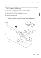
Remove air valve cap (1) and valve core (2) from purging valve stem (3).
2
Remove purging valve stem (3) from M118A2/M118A3 elbow telescope (4) and strap (5) from purging valve
stem (3) and from air valve cap (1).
3
Remove machine screw (6) from exit port.
4
Remove self-locking nut (7) and machine screw (8). Discard self-locking nut.
5
Remove loop clamp (9) and optical eyeshield (10).
6
Unscrew and remove lamp (11) in cover access (12) of M118A2 elbow telescope only.
7
Notify support maintenance for replacement of LEDs if damaged for M118A3 elbow telescope only.
8
Remove setscrew (13) and knob (14).
b.
Inspection
1
Notify support maintenance if lens (15) is scratched or cracked.
2
Notify support maintenance if eyepiece arm (16) does not move easily or remain in locked position.
3
For additional inspections refer to TM 9–2350–311–10.
c.
Assembly
1
Slide loop clamp (9) on optical eyeshield (10) and assemble to eyepiece end of M118A2/M118A3 elbow tele-
scope (4).
2
Secure optical eyeshield (10) with machine screw (8) and new self-locking nut (7).
Back to Top


