TM-9-2350-311-20-2 - Page 678 of 828
TM 9–2350–311–20–2
18–10
Change 2
18–3 M145/M145A1 TELESCOPE MOUNT — CONTINUED
c.
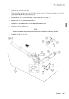
Disassembly of Linkage Assembly
1
Remove four cap screws (4) and four lockwashers (11) from arm (12). Discard lockwashers.
2
Remove plate (13), plate (14), and two gripspring sets (15) (four gripsprings).
3
Remove two self-locking nuts (16) from shouldered shaft (17). Using brass drift punch and hammer, tap
shouldered shaft from arm (12). Discard self-locking nuts.
4
Separate arm (12) from link (18) and remove two gripspring sets (19) (four gripsprings), and two washer
bearings (20).
5
At bottom of link (18), remove cap screw (21) and lockwasher (22). Discard lockwasher.
d.
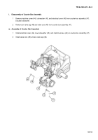
Inspection of Linkage Assembly
1
Inspect gripsprings (15 and 19) for evidence of spinning. Replace if defective.
2
If plate (13) shows evidence of being dented or bent, replace.
3
Inspect all threaded parts for stripped or missing threads. Replace as needed.
e.
Assembly of Linkage Assembly
1
Install two washer bearings (20) with the raised portion against ball bearing (23).
2
Install bottom link (18) into arm (12).
3
Insert shouldered shaft (17) into arm (12), and tap into place using brass drift punch and hammer.
4
Install two gripspring sets (19) with the flat sides of the external springs positioned against washer bearings
(20) and internal springs towards self-locking nut. Install two new self-locking nuts (16).
5
Install new lockwasher (22) and cap screw (21) at bottom of link (18).
6
Install two gripspring sets (15) in arm (12) with the flat sides of the external halves together.
7
Place plate (13) on arm (12) and plate (14) on the opposite side of arm.
8
Install four new lockwashers (11) and four cap screws (4).
Back to Top


