TM-9-2350-311-20-2 - Page 686 of 828
TM 9–2350–311–20–2
18–16.2
Change 2
18–3 M145/M145A1 TELESCOPE MOUNT — CONTINUED
n.
Installation of M145/M145A1 Telescope Mount – Continued
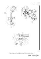
8
Place M1A1 gunner’s quadrant (50) with zero reading (end-for-end-correction applied) on M145/M145A1
telescope mount (6) quadrant seats (52).
9
Center bubble on M145/M145A1 telescope mount (6) cross-level vial (53).
10
If bubble (54) in M1A1 gunner’s quadrant (50) is centered, tighten four cap screws (4) on linkage assembly
(5). If bubble is not centered, loosen four cap screws (4) on linkage assembly (5). Tap counter box assembly
(47) to center bubble in M1A1 gunner’s quadrant.
11
Tighten eccentric shaft (55) to 12 o’clock position.
12
Check synchronization of M145/M145A1 telescope mount (para 18–4c.).
13
Purge counter box assembly (47) (TM 750-116).
6
50
54
53
52
55
6
5
4
Back to Top


