TM-9-2350-311-20-2 - Page 677 of 828
TM 9–2350–311–20–2
Change 2
18–9
3
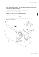
From inside cab, reach between M145/M145A1 telescope mount (6) and roof of cab, and disconnect electri-
cal connector (7) located on upper left side of M145/M145A1 telescope mount.
NOTE
For ease of assembly, do not allow lower assembly of linkage assembly to rotate.
4
Remove linkage assembly (5) from M145/M145A1 telescope mount (6).
NOTE
Webbing strap must be used to help hold M145/M145A1 telescope mount in keyway until all cap
screws are removed.
5
Support M145/M145A1 telescope mount (6) with webbing strap (8) around M145/M145A1 telescope mount
and mounting plate (not shown). Loosen two cap screws (9) and two cap screws (9.1), but leave enough of
the threads holding to support M145/M145A1 telescope mount.
WARNING
M145/M145A1 telescope mount weighs 96 pounds (43.5 kg). The following steps require two per-
sonnel to prevent bodily injury or equipment damage.
6
Hold M145/M145A1 telescope mount (6) in mounting plate keyway (hidden) and remove two cap screws (9),
two cap screws (9.1), and four lockwashers (10). Discard lockwashers.
7
While securely holding M145/M145A1 telescope mount (6) in keyway of mounting plate (hidden), remove
webbing strap (8).
8
Carefully lower M145/M145A1 telescope mount (6) to floor of cab.
1
2
3
5
4
7
6
9
10
9.1
10
8
Back to Top


