TM-9-2350-311-20-2 - Page 684 of 828
TM 9–2350–311–20–2
18–16
Change 2
18–3 M145/M145A1 TELESCOPE MOUNT — CONTINUED
n.
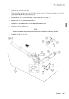
Installation of M145/M145A1 Telescope Mount
1
Two personnel raise M145/M145A1 telescope mount (6). One mechanic holds M145/M145A1 telescope
mount in keyway of mounting plate (not shown). The second mechanic secures M145/M145A1 telescope
mount to plate by attaching webbing strap (8) to M145/M145A1 telescope mount.
NOTE
•
Two longer screws go in top holes.
•
Tighten four cap screws to 80–90 lb-ft (108–122 N
.
m). After installation, M145/M145A1 tele-
scope mount must be synchronized (para 18–4) .
•
Leave a 1 inch (2.54 cm) gap between linkage assembly and M145/M145A1 telescope mount. If
gap is less than 1 inch (2.54 cm), loosen four cap screws on linkage assembly plates. Move
linkage assembly in or out until gap measures 1 inch (2.54 cm). Tighten four screws and re-
check measurements.
2
Install two cap screws (9), two cap screws (9.1), and four new lockwashers (10) on M145/M145A1 telescope
mount (6) and remove webbing strap (8). Torque cap screws 80 to 90 ft-lb (108 to 122 N
.
m).
3
Connect electrical connector (7).
47
7
6
9
10
9.1
10
8
Back to Top


